[BFG Tech] “GS” Series
USER’S MANUAL
Thank you for choosing to purchase this BFG POWER SUPPLY UNIT (PSU). Please read this manual carefully prior to installing your new PSU.
To ensure an increased lifetime for your PSU, as well as your entire computer system, we would like to draw your attention to the following precautions concerning environmental conditions:
Make
sure your computer system is not located near a furnace, radiator or
any other type of heat producing device.
Ensure
that your computer system is not located near any devices that
produce a magnetic field.
Make
certain your computer system is not exposed to moisture or high
humidity.
Confirm
that your computer system is not located where airflow can be
obstructed by the build up of dust particles.
Make
sure not to locate your computer system where it can be exposed to
prolonged vibration.
Keep
your computer system out of direct sunlight.
Provide a stable AC input to your computer system. A surge protector, line conditioner or uninterruptible power source (UPS) is strongly recommended.
COMPATIBILITY:
BFG
power supplies are compatible with:
The
ATX12V 2.3 and prior specifications.
Graphics cards requiring PCI Express® power connectors (please check your graphics cards’ configuration for number of connectors required, etc.).
BFG
power supplies feature:
Dual
+12V output capability, limited to no more than 240VA output to
abide by UL and EN 60950 safety requirements for improved safety and
reliability.
One
or two PCI Express®
connectors (depending on model) for high-end graphics cards.
Supports
either 4-pin ATX12V or 8-pin EPS12V power connectors for supplying
power to CPU.
Typical
efficiency of over 80%.
140MM
sleeve bearing cooling fan.
“Thermal
Control Technology” thermostatically adjusts fan speed based on
load and temperature in order to maintain as low and as quiet of a
fan speed as possible.
100%
Hi-Pot and Burn-In testing.
Industrial grade OCP (Over Current Protection), OPP (Over Power Protection), OVP (Over Voltage Protection) and SCP (Short Circuit Protection) protective circuits.
To
make sure your power supply has all of the appropriate connections
for your computer system and that it is connected properly, please
check the documentation included with your motherboard, peripherals
and/or computer system.
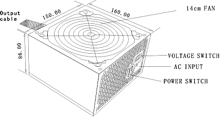
This BFG power supply conforms to the ATX, ATX12V and PS/2 standard for power supply size: 150mm x 86mm x 160mm (see below).
The power supply unit truly has no “right side up”, although care should be exercised when mounting the unit inside a chassis to ensure the unit’s intake fan receives ample air flow.
INSTALLATION:
1.
Ensure you are properly grounded by touching your system case while
the unit is still plugged into the wall. An ESD wrist strap or
work-mat are recommend whenever you are working inside you computer
system. Once grounded, unplug the power cord from your existing
power supply unit.
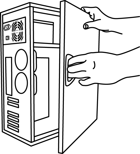
2. Open your system case (please refer to the manual that came with your computer system or chassis).
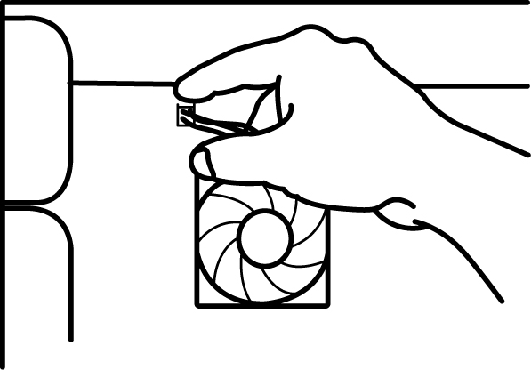
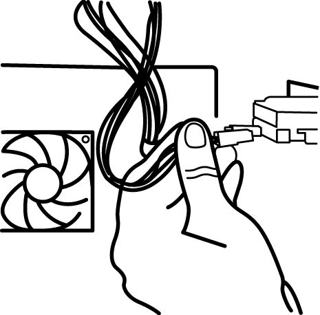
3. Locate each power connector in use by the motherboard and peripherals such as DVD-ROMs, graphics cards, hard drives, floppy drives, etc. Unplug power from each device, keeping track of each connection as you will need to re-connect them after installing your new BFG power supply.
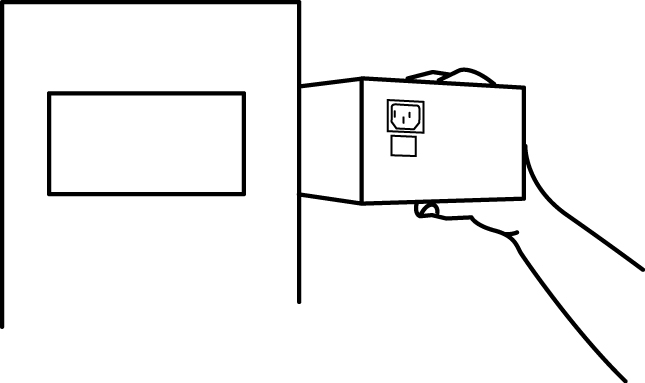
4. Remove the screws holding your existing power supply in place – be careful to support the power supply as it comes loose so it does not cause damage to any components.
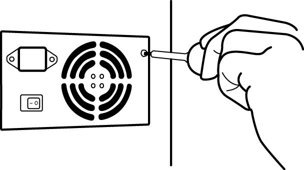
5. Insert your new BFG power supply, lining up the mounting holes and tighten the screws.
6. Locate the matching power connector to each of the components you disconnected in step 3 and determine which power supply connector will reach each component. Careful planning here can avoid the “jumbled wire” look and improve air flow throughout the case.
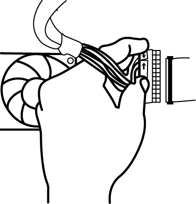
7. Connect power to the motherboard and each component requiring power. For motherboards with a 24-pin main connector, please make sure that the 20-pin and 4-pin connector sections on that cable are inserted together. For motherboards that use an 8-pin CPU +12V power connector, please make sure that both 4-pin connector sections on that cable are inserted together.
NOTE: 4-pin peripheral connectors have a flat bottom and angled edges on the opposite side and will only fit one way. NEVER force the connectors together as permanent damage may occur!
8. Close your system case.
9. Make sure the red 115/230V switch on the back of the power supply unit is set to the correct AC input voltage for your country (115V is typical for the USA).
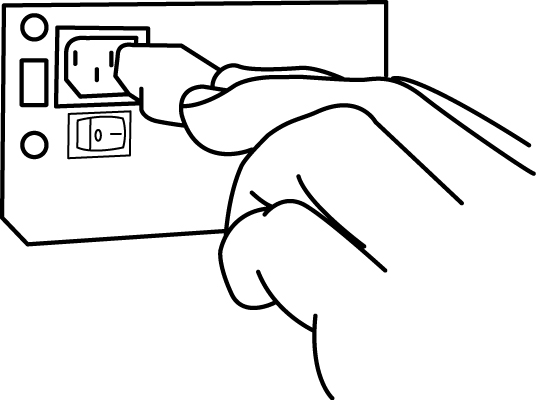
10. Plug the power cord into your new BFG power supply and flip the I/O power switch on the back of the unit to the “I” position. You are now ready to power up your computer system.
SPECIFICATIONS:
WARNING: Opening your BFG power supply unit voids the product’s warranty. Any service performed by an individual other than a BFG Technologies representative voids the product’s warranty. Any service performed on the unit should only be done by a trained and skilled individual.
AC Input voltage:
|
Parameter |
Minimum |
Nominal |
Maximum |
Unit |
|
Voltage input (115VAC) |
90 |
115 |
132 |
VRMS |
|
Voltage input (230VAC) |
180 |
230 |
264 |
VRMS |
|
Voltage input Frequency |
47 |
--- |
63 |
Hz |
Input Over Current Protection:
This BFG power supply unit incorporates one input fuse on the LINE side for input over current protection to prevent damage to the power supply and meet product safety requirements. Fuses should be slow blow type or equivalent to prevent nuisance trips. AC inrush current shall not cause the AC line fuse to blow under any conditions.
Efficiency:
This power supply unit is capable of 80% or higher efficiency at FULL load. The efficiency of the power supply should be tested at nominal input voltages (115VAC or 230VAC).
Protection, Safety and Security:
BFG power supplies feature multiple protections. When abnormal circumstances occur, the power supply unit will automatically turn off (latch) to avoid potential damage to itself and other system components. Typically, component malfunction or user error is the cause for the unit to latch into protection mode. In such circumstances, please flip the unit’s I/O (power) switch to the “O” position, disconnect the power supply from the wall outlet and check all peripherals for damage or an occurrence of a short to ground.
Troubleshoot by removing non-essential components (non-boot drives, extra PCI cards, etc.). Check the PSU for overheating by simply touching the side of the unit. If it feels very hot, the PSU may not be getting enough air flow or the PSU fan itself may have malfunctioned. To confirm, wait for the power supply to cool down before trying to power up again.
After locating and correcting the fault, reconnect the AC power cord to the wall outlet and flip the unit’s I/O switch back to the “I” position.
Output Voltage Regulation:
|
Output |
Range |
Min. |
Nom. |
Max. |
Unit |
|
+12V1DC |
±5% |
+11.4 |
+12.00 |
+12.60 |
Volts |
|
+12V2DC |
±5% |
+11.4 |
+12.00 |
+12.60 |
Volts |
|
+5VDC |
±5% |
+4.75 |
+5.00 |
+5.25 |
Volts |
|
+3.3VDC |
±5% |
+3.14 |
+3.30 |
+3.47 |
Volts |
|
-12VDC |
±10% |
-10.80 |
-12.00 |
-13.20 |
Volts |
|
+5VSB |
±5% |
+4.75 |
+5.00 |
+5.25 |
Volts |
Output Ripple and Noise:
Ripple and noise are defined as periodic or random signals over a frequency band of 10Hz to 20MHz.
|
+3.3 V |
+5 V |
+12 V1 |
+12V2 |
-12 V |
+5 VSB |
|---|---|---|---|---|---|
|
50 |
50 |
120 |
120 |
120 |
50 |
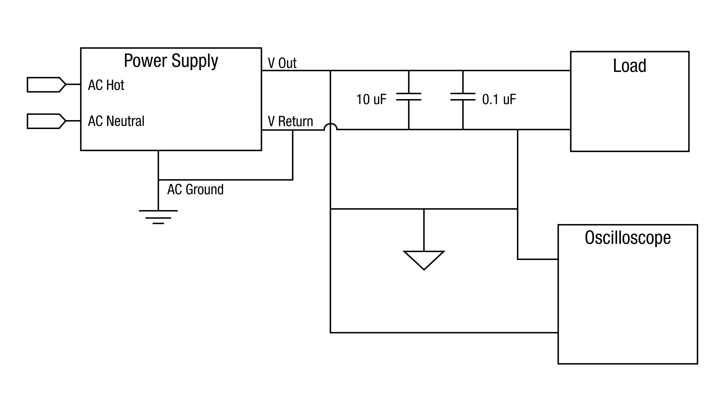
Measurements shall be made with an oscilloscope with 20MHz of bandwidth. Outputs should be bypassed at the connector with a 0.1uF ceramic disk capacitor and a 10uF electrolytic capacitor (as shown in next diagram) to simulate system loading.
The load must be isolated from the ground of the power supply.
General Note:
1. Load the output with its minimum load current.
2. Connect the probes as shown.
3. Repeat the measurement with maximum load on the output.
Filter Note:
0.1uF – Suggest Kemet C1206C104K5RAC or equivalent +/- 10%, 1206 pkg, 50V, X7R
10uF – Suggest Vishay 293D106X0025D2T or equivalent +/- 20%, D Case, 25V, tantalum
Oscilloscope Note:
Use Tektronix TDS460 or equivalent and a P6046 probe or equivalent.
Output Protection:
If the power supply latches into a shutdown state (due to OCP, OVP or SCP) the unit will only return to normal operation after the fault has been removed and the remote signal is reset for a minimum of 1 second (or remove the AC input for a minimum of 10 seconds).
Over Voltage Protection (OVP):
If any output voltage exceeds its limit, the power supply shall shut down and latch into OVP.
Short Circuit Protection (SCP):
An output short circuit is defined as any output impedance of less than 0.1 ohms. The power supply shall shut down and latch until the short is removed.
Over Current Protection (OCP):
If the load on a particular rail exceeds a predetermined OCP limit, the power supply shall shut down and latch.
DC Output Connectors:
Pin side view, not to scale:
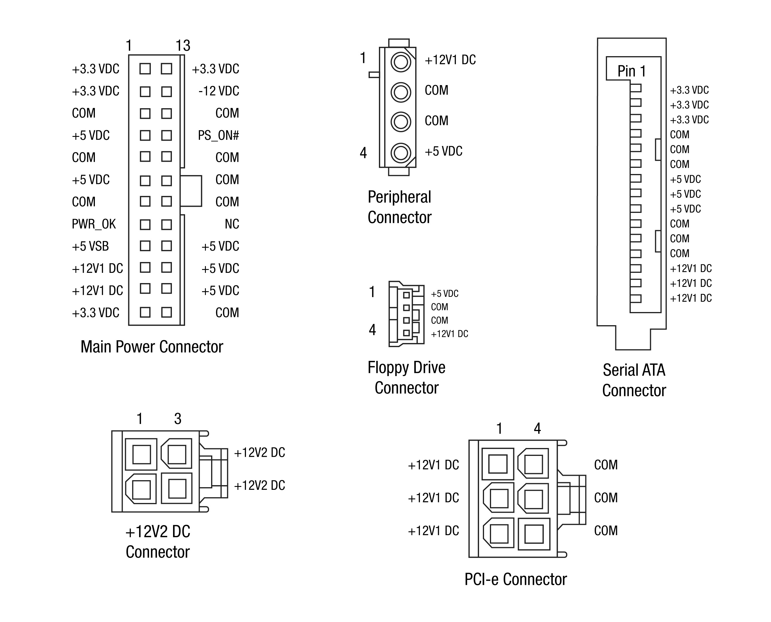
ATX Main Power Connector:
|
|
24-pin configuration supports new-generation ATX motherboards (ATX12V). Pins 11, 12, 23 and 24 can be removed for older ATX motherboards. |
|
Pin |
Signal |
18 AWG Color |
Pin |
Signal |
18 AWG Color |
|
1 |
+3.3 VDC |
Orange |
13 |
+3.3 VDC |
Orange |
|
2 |
+3.3 VDC |
Orange |
14 |
-12 VDC |
Blue |
|
3 |
COM |
Black |
15 |
COM |
Black |
|
4 |
+5 VDC |
Red |
16 |
PS_ON |
Green |
|
5 |
COM |
Black |
17 |
COM |
Black |
|
6 |
+5 VDC |
Red |
18 |
COM |
Black |
|
7 |
COM |
Black |
19 |
COM |
Black |
|
8 |
PWR OK |
Gray |
20 |
-5 V |
N.C. |
|
9 |
5 VSB |
Purple |
21 |
+5 VDC |
Red |
|
10 |
+12 V1 |
Yellow |
22 |
+5 VDC |
Red |
|
11 |
+12 V1 |
Yellow |
23 |
+5 VDC |
Red |
|
12 |
+3.3 VDC |
Orange |
24 |
COM |
Black |
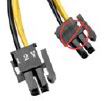
CPU +12V Power Connector (8-pin):
|
|
Combine two 4-pin connectors together to form 8-pin connector. 8-pin configuration supports multiple core/multiple processor configurations in server/workstation systems. |
|
Pin Signal Color |
Pin Signal Color |
|---|---|
|
1 COM Black |
5 +12V2DC Yellow/Black Stripe |
|
2 COM Black |
6 +12V2DC Yellow/Black Stripe |
|
3 COM Black |
7 +12V2DC Yellow/Black Stripe |
|
4 COM Black |
8 +12V2DC Yellow/Black Stripe |
CPU +12V Power Connector (4-pin):
|
|
4-pin configuration supports most ATX/BTX systems. The second set of 4-pins that make up the 4+4-pin connector are not used in computer systems utilizing only the 4-pin connector. |
|
Pin Signal Color |
Pin Signal Color |
|---|---|
|
1 COM Black |
3 +12V2DC Yellow/Black Stripe |
|
2 COM Black |
4 +12V2DC Yellow/Black Stripe |
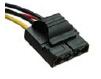
4-pin Peripheral Connector:
|
|
For IDE/SCSI drives with traditional 4P power in socket. |
|
Pin Signal Color |
Pin Signal Color |
|---|---|
|
1 +12V1DC Yellow |
3 COM Black |
|
2 COM Black |
4 +5VDC Red |
Floppy Drive Connector:
|
|
For floppy drives and similar devices. |
|
Pin Signal Color |
Pin Signal Color |
|---|---|
|
1 +5VDC Red |
3 COM Black |
|
2 COM Black |
4 +12V1DC Yellow |
Serial ATA Power Connector:
|
|
15-pin connector for new generation SATA drives. |
|
Pin |
Signal |
18 AWG Color |
|
1-3 |
+3.3VDC |
Orange |
|
4-6 |
COM |
Black |
|
7-9 |
+5VDC |
Red |
|
10-12 |
COM |
Black |
|
13-15 |
+12V1 |
Yellow |
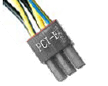
6-pin PCI Express® Connector:
|
|
6-pin PCI Express® connector provides +12V1 output for PCI-E x16 graphics cards.
|
|
Pin Signal Color |
Pin Signal Color |
|---|---|
|
1 COM Black |
4 +12V1DC Yellow |
|
2 COM Black |
5 +12V1DC Yellow |
|
3 COM Black |
6 +12V1DC Yellow |
TECHNICAL SUPPORT:
If you have any installation problems please contact our technical support which is available 24 hours, 7 days a week. In the US and Canada call toll free 1-866-BFG-FIXX (234-3499). Outside the US call (toll call, charges apply) 00+1–630-637-2459. E-mail at support@bfgfixx.com.
WARRANTY:
BFG Technologies is proud to warrant the original purchaser of this power supply unit that the Product will be free from defects in material or workmanship for a period of one (1) year from the original date of purchase of the product, when given normal wear and proper usage. This warranty is valid if the product:
Was
not damaged while being installed.
Was
not damaged by software or hardware from a company or individual
other than BFG Technologies or by motherboard incompatibility.
Was
operated in accordance with BFG Technologies specifications,
instructions and any technical support directions.
Was
not modified or damaged by tampering, user error, accident,
disaster, abuse, misuse, power application, alteration, repair,
modification, a fix or replacement by someone other than BFG
Technologies.
Third party products, such as add-in graphics cards, and other system components using this Product are not be covered by this warranty.
BFG
Technologies' liability under this warranty, or in connection with
any other claim relating to the Product, is limited to the repair or
at BFG Technologies option, the replacement of the portion of the
Product which was defective in material or workmanship. This warranty
does not apply to any software component.
You assume the risk
of loss in transit and the returned Products shall be the sole
property of BFG Technologies. BFG Technologies warrants the repaired
or replaced Products will be free from defects in material or
workmanship.
EXCEPT AS EXPRESSLY STATED ABOVE, BFG Technologies MAKES NO WARRANTY, EXPRESS OR IMPLIED, WHETHER OF MERCHANTABILITY, NON-INFRINGEMENT OF INTELLECTUAL PROPERTY, FITNESS FOR ANY PARTICULAR PURPOSE OR USE, OR OTHERWISE ON THE PRODUCTS, OR ANY PARTS OR TECHNICAL ASSISTANCE OR OTHER LABOR FURNISHED.
BFG Technologies reserves the right to inspect and verify the defectiveness of any product returned. Please allow 48 hrs processing time once item has been received by BFG, and 3-5 days for shipping of the replacement product (shipped ground).