Back to Contents Page

Microprocessor Thermal-Cooling Assembly

Dell™ Latitude™ D505 Service Manual


Removing the Microprocessor Thermal-Cooling Assembly

CAUTION: Before performing the following procedures, read the safety instructions in your Product Information Guide.
NOTICE: To avoid electrostatic discharge, ground yourself by using a wrist grounding strap or by periodically touching an unpainted metal surface (such as the back panel) on the computer.
NOTICE: Disconnect the computer and any attached devices from electrical outlets, and remove any installed batteries.
  1. Follow the instructions in "Preparing to Work Inside the Computer."

  2. Remove the keyboard.

  3. Disconnect the display cable from the display cable connector on the system board.

  4. Release the two antenna cables from the two antenna-securing clips.

  5. Disconnect one antenna cable from the display by holding the two gold antenna connectors and gently pulling them apart. Then disconnect the other antenna cable. (The gold antenna connectors on each cable are keyed to ensure that they are correctly reconnected.)

1

antenna connectors (4)

2

display cable connector

3

display cable connector on system board

4

antenna securing clips (2)

5

antenna cables (2)

NOTE: You can remove the microprocessor thermal-cooling assembly with the fan attached.
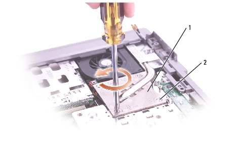
  1. Loosen in consecutive order the four captive screws, labeled "1" through "4," that secure the microprocessor thermal-cooling assembly to the system board.

1

microprocessor thermal-cooling assembly

H1309

2

captive screws (4)


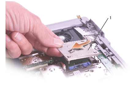
  1. Lift up the microprocessor thermal-cooling assembly and remove it from the system board.

1

microprocessor thermal-cooling assembly

H1309

Installing the Microprocessor Thermal-Cooling Assembly

  1. Slip the left side of the microprocessor thermal-cooling assembly underneath the palm rest and then place the assembly over the microprocessor.

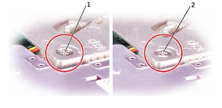
  2. Tighten the four captive screws, labeled "1" through "4," in consecutive order. While tightening the screws, ensure that the cooler plate is not higher than the captive screw head.

1

incorrectly installed heat sink

2

correctly installed heat sink

  1. Reconnect the two antenna cables and then secure them into the two antenna-securing clips.

  2. Reconnect the display cable to the display cable connector and then secure the display cable in its three display-cable routing clips.


Back to Contents Page